
Photo-Etching Technique – Mini-Howto
This is a short guide to help anyone create ultra-fine sheet metal parts for model making at home using hobby tools. Apart from a PC with an inkjet printer, only a few special accessories and a handful of off-the-shelf chemicals are needed.
Photo-etching technique, what is it?
Section titled “Photo-etching technique, what is it?”The objective of the photo-etching technique is to manufacture extremely intricate metal parts with minimal effort. A well-known area of application is the production of printed circuit boards (PCBs) for electronic assemblies. However, photo-etching can just as easily be used to make very fine metal structures for model making.
Regardless of the finished product, the process is always the same:
- Using a light mask, the structure to be etched is transferred to the workpiece, which is coated with a photosensitive photoresist.
- The developer bath removes the resist outside of the structure. Now, the workpiece retains an etch-resistant coating only in those areas that form the final structure.
- In the etching bath, the uncoated sections of the workpiece are etched away.
Ultimately, only the desired structure remains.
The workpiece does not necessarily have to be etched through completely. It is also possible to etch only parts of the material cross-section, resulting in a relief. Naturally, flat nets of three-dimensional shapes can also be produced, which are later folded into their final shape by bending.
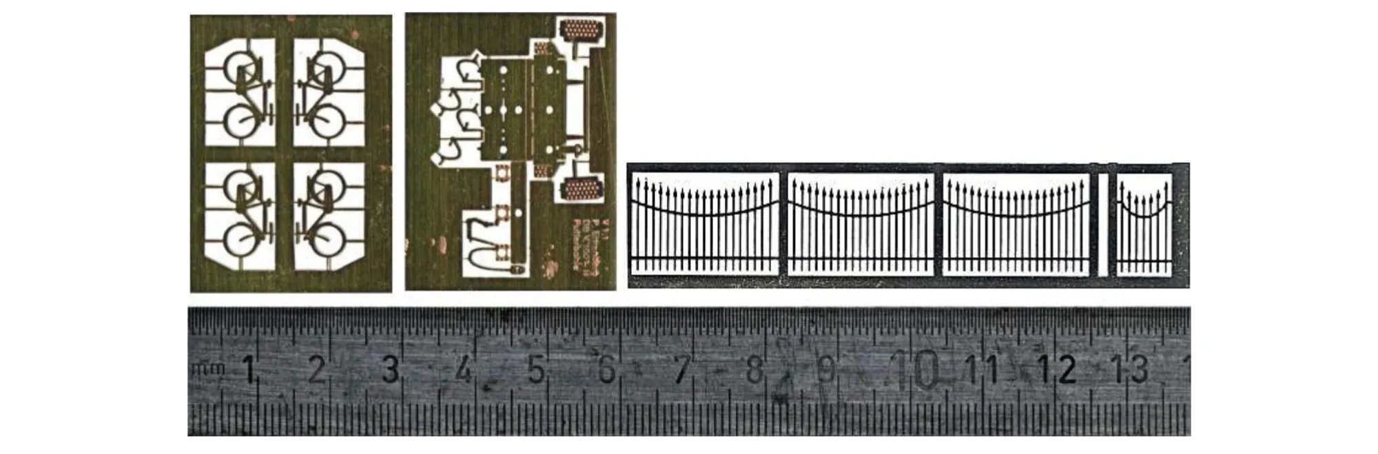
Examples of etched parts (left to right): N scale bicycles in 0.2 mm brass, buffer beam for Minitrix DB V 100 in 0.2 mm brass, N scale fence in 0.1 mm nickel silver.
What do I need for etching?
Section titled “What do I need for etching?”For your initial attempts, you can get by with a relatively modest setup. First, however, you need to consider where you want to etch. You will be handling toxic, corrosive chemicals – spills can never be entirely ruled out. The kitchen or living room are out of the question. The bathroom might be an option, provided you don’t have a partner, or have a very forgiving one.
If available, a workshop is an ideal location. However, it should have a mains water supply and a drain.
Regardless of where you perform the etching, it should always be done inside a large tray or basin. If something tips over, you won’t end up with a mess all over the floor.
Basic Equipment:
Section titled “Basic Equipment:”- 1 UV light lamp for exposure
- 1 glass plate to weigh down the film during exposure
- 1 developer tray (plastic, photo supplies)
- 1 etching tray (ceramic, homeware) or heat-resistant beaker (lab equipment)
- 2× 1-litre containers to store the developer and etching solutions (plastic, photo supplies)
- 2 pairs of rubber gloves
- 1 safety goggles
- 1 set of old clothes
- Plastic clothes pegs
- 1 large plastic tub
A darkroom is not required. Work can be carried out under subdued daylight or artificial light.
It is assumed that you have access to a computer with an inkjet printer and a vector graphics program.
Consumables:
Section titled “Consumables:”- Developer (matching the resist)
- Etchant (various options, see below)
- Presensitised metal sheet
- Inkjet-compatible OHP film
Safety notice – Must read!
Section titled “Safety notice – Must read!”The metal sheet
Section titled “The metal sheet”You can coat the metal sheet with photoresist yourself (available as a spray paint). However, this is not recommended, as dust particles during spraying will render the coating unusable. It is better to buy commercially produced, double-sided presensitised metal sheets. Provided it is kept cool, the sheet has a shelf life of around one year.
Presensitised sheets are available in brass, nickel silver, and copper in thicknesses ranging from 0.1 to 0.8 mm. Nickel silver sheet is spring-hard and therefore quite resistant to rough handling even with delicate parts. However, it snaps easily when bent.
Full through-etching works up to a thickness of approx. 0.3 mm. Thicker sheets can only be surface-etched. As a rule of thumb, minimum feature sizes can match the thickness of the material used (e.g., for a 0.1 mm sheet, features down to a minimum of 0.1 mm; for a 0.3 mm sheet, down to 0.3 mm). Attempting to etch smaller features leads to undercutting: the etchant acts not only vertically to the surface, but in all directions, creeping under the masked areas.
Positive vs. Negative Resist:
Section titled “Positive vs. Negative Resist:”- Positive Material: Exposure and development remove the exposed areas. The masked, unexposed structure remains intact and survives the etching bath. (Standard approach)
- Negative Material: Exposure and development remove the masked, unexposed areas. The exposed areas remain. (Advantageous for brick wall reliefs, for instance, as only the mortar joints need to be printed as black lines on the artwork).
The sheet comes covered on both sides with lightproof protective film, which must be removed after cutting to size and prior to exposure.
Cutting to size: Best done using jeweller’s tin snips (the sheet bends easily) or cut using a fine saw blade.
After cutting and removing the protective film, insert the metal sheet into the film envelope and fix it in place with a small piece of adhesive tape.
Producing the film
Section titled “Producing the film”The most laborious step in photo-etching is designing the light mask (the film artwork) on the computer.
For this, we need a drawing program. Ideally, it should possess all of the following features:
- It is vector-based, means you can change single objects (eq. lines) by selectin them and than moving e.g. enpoints.
- It can draw lines of a defined length and thickness.
- It can draw straight lines, arcs, rectangles, and circles.
- It can fill areas with (black and white) color.
- It either offers the resolution we require (regarding line thickness and snapping grid), or it allows us to create the drawing at a 10:1 scale and print it at 10% size.
- It supports layers so that we can edit individual parts of the drawing separately. For the overall picture, the program stacks the layers on top of each other in a defined order.
- The program can copy and mirror a drawing. We need this to produce a two-sided film (one for the top side and one for the bottom side of the sheet metal).
We don’t need colors. We draw in black and white, where only the black areas are printed onto the film during printing. The white areas remain transparent.
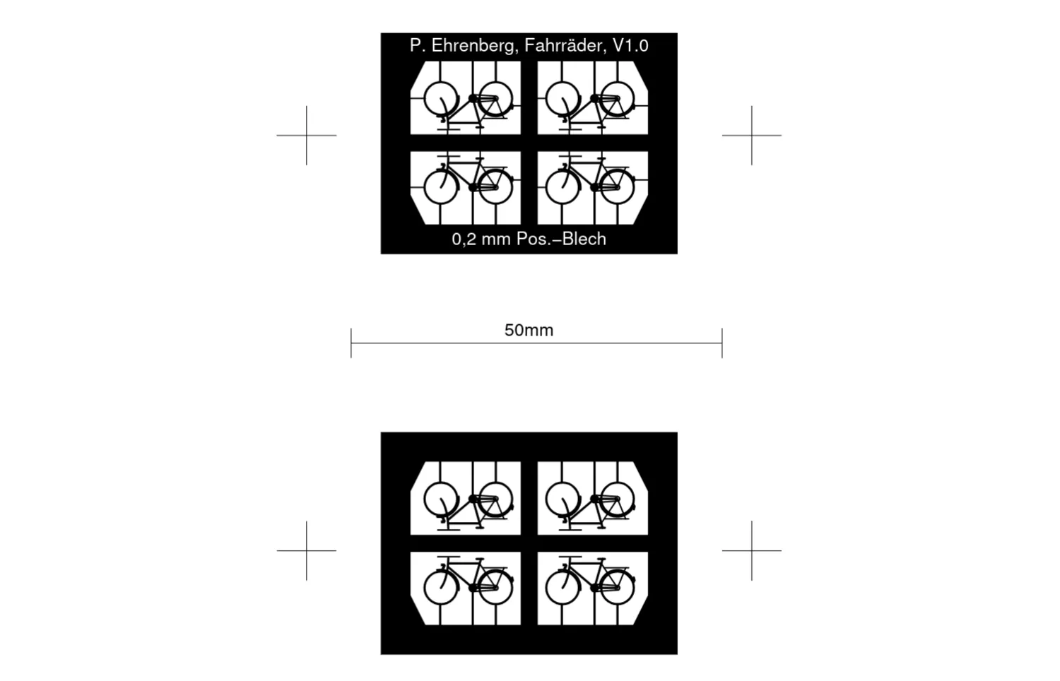
To begin with, you should start with small parts. The drawing above gives an example. The drawing was made for 0.2 mm positive sheet metal. Therefore, the minimum possible line weight is 0.2 mm.
A decisive step in the film design is mirroring the drawing. The film will later be made into an envelope/pouch. To do this, the film is folded along the 50 mm line shown in the example. The two mirrored drawings must align exactly on top of each other.
If you do not want to etch all the way through everywhere, the drawings for the top and bottom sides will not be identical. If you have a drawing program with layers, it makes sense to place the drawing elements that only go on one of the two sides onto separate layers. After mirroring, the layers that are redundant on each respective side are then deleted.
The bicycle drawing in was built up using layers. From the foreground to the background, these are:
- The bicycles themselves are located on the foremost layer.
- Located on the layer behind it are those holding tabs that are masked on only one side of the sheet metal. They will be half-etched through from the opposite side so that they can be easily detached later. For 0.1 mm sheet metal, half-etching is not necessary (nor is it strictly necessary for 0.2 mm).
- Behind that lies the white area inside the etching frame. It should fit as closely as possible to the structure to be etched. This way, less material needs to be etched away, which preserves the etching bath.
- The second to last layer holds the etching frame. It plays an important role because it supports our etched structure and keeps it from falling into the etching bath at the end. The frame should be wide enough so that we can securely grip it with a clothespin and submerge the whole piece into the etching bath.
- Finally, on the rearmost layer lies the 50 mm line and the alignment marks. The 50 mm line serves solely for scale checking during printing. The alignment marks are used later to align both film parts precisely on top of one another.
If you want to etch a flat pattern (unfolded layout) of a three-dimensional object, you will need bend lines. For this purpose, a (single-sided) groove is etched into the sheet metal. Long edges are easier to bend if you etch a slot and leave behind only a few more or less wide connecting tabs of half the material thickness.
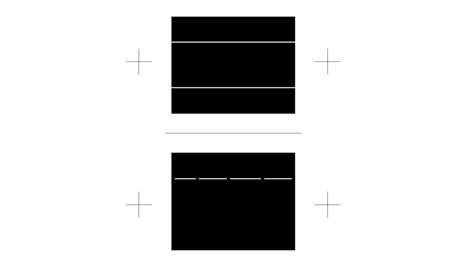
Two different options for bend lines: The inside edge on the film is created using a slot with holding tabs. The outside edge is created by a single-sided etched groove.

View of the sheet metal cross-section: Bending is done such that the groove ends up on the outside of the bend.
In both cases, the groove or slot width should equal the single sheet metal thickness for 90° bends and twice the sheet metal thickness for 180° bends. Keep in mind that white lines inside black areas tend to bleed/shrink slightly on inkjet printers.
Once the drawing has been created, the most time-consuming work is already done. Now, a film is produced from the drawing. For this step, we have the following options:
- We send the drawing as a PS, EPS, or PDF file to a photolithography service provider. They will create an imagesetter film with a resolution of 2400 dpi for us. The result is top-notch. However, at 10-20 € per A4 sheet, it is also quite expensive.
- Printing with an inkjet printer on overhead transparency film.
Prints from laser and thermal printers – even on special transparency films – are usually too pale and not very well suited.
Printing it yourself with an inkjet printer is also not particularly cheap at 2-5 €. Still, it delivers decent results that can at least serve to determine whether the drawing is correct. The prerequisites are a modern inkjet printer with a resolution of at least 600 dpi and the use of special overhead transparency films designed for inkjet printers. When printing, do not forget to select the paper type “Transparency” in the print dialog.
A film pouch is now made from the film sheet. It’s simple: the film is cut between the two drawings for the top and bottom sides. You should cut about half a cm off-center. We tape the larger film piece to a bright surface (e.g., a windowpane) using adhesive tape. Now we take the other film piece, position it precisely over the first using the alignment marks, and fix it to the first piece with a strip of adhesive tape.
The printed side of an inkjet transparency (or the emulsion side of an imagesetter film) should face inward. When the sheet metal is placed into the pouch for exposure, the black layer will sit directly against the metal. Otherwise, the exposure would result in blurring/under-cutting.
The metal sheet is sharp. So take care, especially with inkjet films, and do not scratch the film.
Exposure
Section titled “Exposure”You do not need a darkroom for exposure. The photoresist is not particularly light-sensitive. It is exposed using UV light. The maximum sensitivity of the photoresist is at a wavelength of 440 nm. We need an intense UV light source. There are dedicated exposure units for this purpose. They are generally equipped with UV fluorescent tubes. Such a unit costs around 200 €. Cheap alternatives are special UV incandescent bulbs that you simply screw into a socket and hang by the cable, e.g. Osram Nitraphot S 250 W, or other UV lamps. However, you have to expect longer exposure times. I use a homemade lamp myself. It has a mercury-vapour bulb of the type found in facial tanners.
Depending on the intensity of the light source, an exposure time of approximately 1–15 minutes is required. If you do not use a dedicated exposure unit, but a simple UV lamp instead, the distance to the sheet metal being etched should be around 30 cm.
The exposure time must be long enough. The photoresist is then particularly well exposed and can be developed quickly and easily. Of course, exposure of the masked areas must not already occur during this process. With emulsion films from a professional imagesetter, this risk is virtually non-existent. With inkjet printer films, you need to be a little careful and experiment. Even if the exposure time turns out to be too short, the resist can usually still be developed. However, this takes a long time, and there is therefore a risk that masked areas will also be attacked by the developer.
For exposure, the film pouch with the fixed sheet metal is placed on a flat surface and weighted down with the glass plate so that the film and sheet metal are pressed firmly together.
Light on – light off!
After exposing the first side, the reverse side must also be exposed.
Light on – light off!
Now carefully remove the etched part from the film pouch, taking care once again not to scratch the film. The exposed areas on the etched part can be identified by a slight color change.
Developing
Section titled “Developing”Different developers are required for positive and negative photoresist-coated sheet metal. It is best to buy the appropriate developer from the same supplier from whom you obtain the sheet metal. The chemical comes as an instant powder in a small sachet (10 g) and is dissolved in 1 L of warm water. For use, the developer should be heated to approx. 30–40 °C. The developer is a strong sodium hydroxide (NaOH) solution, which causes chemical burns to eyes and skin – so put on rubber gloves and your safety goggles.
For developing, submerge the exposed sheet metal into the developer. The developing process can be easily observed. The photoresist dissolves, forming purple clouds. The etched part should be gently moved back and forth in the developer bath. If necessary, you can further assist the development with a soft paintbrush (it will not survive the sodium hydroxide bath very often). Looking closely, you can tell when the development process is complete. The process takes 1–3 minutes. After developing, rinse the sheet metal thoroughly with clean water and gently dab it dry with paper towels.
Etching
Section titled “Etching”There are dedicated etching machines available in various designs for the etching process. Professionals use spray etching units. Their price starts at around 400 € upwards. Semi-professional options include vertical etching tanks (cuvettes) in which the etching liquid is agitated by air pumped in through a diffuser. These etching machines feature a thermostatically controlled heating element and a diaphragm pump for the air diffuser. Simple plastic etching tanks can be purchased from around 80 € upwards.
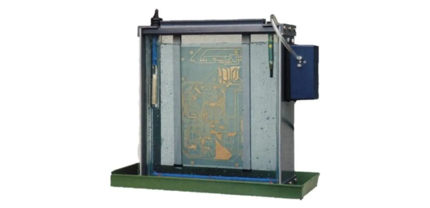
Semi professional etching system
To begin with, however, you can also simply etch in a tray or a small beaker. This works perfectly well if you are only making small etched parts (up to approx. 50 mm edge length) from thin sheet metal (0.1–0.2 mm).
There are three options for the etching solution:
- Iron(III) chloride solution
- Sodium persulfate solution
- Hydrochloric acid and hydrogen peroxide mixture
Professionals use an iron(III) chloride solution. It is the cheapest option, but it has the disadvantage of being completely opaque, making it difficult to monitor the etching process. The sodium persulfate solution is often marketed as a quick-etch agent. In reality, it does not etch any faster than the iron(III) chloride solution. However, it is clear, allowing you to observe the etching process easily.
The hydrochloric acid and hydrogen peroxide mixture is well suited for etching small metal sheets in a beaker. The etchant is very aggressive and the etching proceeds quite rapidly. However, caustic and toxic fumes are produced. You must only use this mixture outdoors. The recipe is:
| Quantity | Ingredient |
|---|---|
| 770 ml | water |
| 30 ml | hydrogen peroxide 30% |
| 200 ml | hydrochloric acid 20% |
Should this etching bath start to lose its potency, it can be reactivated by adding more hydrogen peroxide.
The etching liquid must be kept in constant motion to achieve an even etching result. For the same reason, the etched part should be rotated by 90° at regular intervals when etching in an etching tank. The process takes 5–20 minutes, depending on the sheet metal thickness and the freshness of the etching bath.
To hold the etched part in the etching liquid, I use plastic clothespins in which I have replaced the metal spring with a rubber band. The steel spring would be etched away within minutes.
Under no circumstances should the etched part remain in the etching bath longer than necessary, to avoid under-cutting. This timing is critical, and the end of the etching process should be monitored closely. After etching, rinse the sheet metal immediately with clean water and gently dab it dry with paper towels.
Post-treatment
Section titled “Post-treatment”If the etched part is to be painted, it is certainly recommended to leave the photoresist on. It serves as a good primer. The positive photoresist is solderable. Otherwise, the photoresist can be washed off with methylated spirits (denatured alcohol).
Suppliers
Section titled “Suppliers”| Supplier | Product range / Offerings |
|---|---|
| Saemann Modell- und Ätztechnik Zweibrücker Str. 58 66953 Pirmasens, Germany http://www.saemann-aetztechnik.de/ | Wide selection of presensitised metal sheets • Etchants • Trays • Exposure units • Lamps • Etching machines |
| Conrad Electronic Klaus-Conrad-Str. 1 92240 Hirschau, Germany http://www.conrad.com | Etchants • Trays • Exposure units • Lamps • Etching machines |
| ELV Elektronik AG Postfach 26787 Leer, Germany http://www.elv.de | Etchants • Trays • Exposure units • Lamps • Etching machines |
| Bungard Elektronik GmbH & Co.KG Rilkestrasse 1 51570 Windeck, Germany http://www.bungard.de/ | Presensitised metal sheet supplier (supposedly does not supply private customers) |
fiNe-scale is licensed by [dipe] under
CC BY-SA 4.0


